1. Introduction
This document describes how to install and use the Eclipse based Rich Client for the UNICORE workflow system. UNICORE is a European project that facilitates the access to modern heterogeneous computer networks, so called ‘Grids’. It offers a client-server framework for accessing Grid resources. It has a service oriented architecture (SOA) which means that the functions of the software are grouped into small coherent chunks (named ‘services’) which can be installed on different computer systems.
The client software enables users to create descriptions of work to be performed on the Grid, so called ‘jobs’. A single job usually corresponds to the execution of a computer program on one of the available computer systems in the Grid. Once a job has been created, the UNICORE Rich Client can submit it to a selected computer system. The remote execution of the job can be monitored and output files of the executed program can be downloaded to the user’s computer. In order to accomplish more complex tasks on the Grid, jobs can be embedded into workflows. In our terminology, a workflow is a set of activities (the execution of a single job would be considered an activity), interconnected by transitions that define the order in which the activities must be performed. Workflows can be created and edited graphically. Similar to jobs, they can be submitted to a designated service on the Grid which executes them. Workflow execution can be monitored in multiple ways and resulting output files can be downloaded to the local harddisk. Apart from these basic features, the UNICORE Rich Client offers a bunch of additional functions like browsing and monitoring services on the Grid, managing user certificates, and transferring files to and from Grid storages.
This document is structured into the following parts: [SECTION_INSTALLATION] describes the installation procedure and how to startup the client application. [SECTION_BASIC_USAGE] tries to give a brief overview of the basic features and most frequent use cases of this application. [SECTION_ADVANCED_USAGE_SCENARIOS] introduces and describes more advanced features and functions, while [SECTION_TROUBLESHOOTING] covers common problems and issues. [SECTION_REFERENCE] provides a reference guide to the main pull down menu, user preferences, and command line arguments to the client application.
2. Installation and Startup
2.1. Prerequisites
-
Operating Systems: currently Linux and Microsoft Windows are supported.
[Eclipse’s windowing toolkit, the Standard Widget Toolkit (SWT) directly talks to the operating system’s windowing system. While SWT loses its platform independence through this approach, it allows for seamless integration with the look and feel of different operating systems.]
-
Java Runtime Environment: Sun Java 6 or higher is required.
[Other Java implementations (e.g. by GNU or IBM) are not supported.]
2.2. Procedure
-
Download the installation archive that matches your operating system.
-
Unzip the archive to the desired location.
-
Run the executable called ‘UNICORE_Rich_Client.exe’ (or ‘UNICORE_Rich_Client’, on a Unix/Linux machine). A splash screen will indicate the startup of the client.
-
Specify location and passphrase of the keystore file that holds your certificates (see [SUBSECTION_BASIC_SECURITY] for details about why this is necessary).
3. Basic usage guide
3.1. Welcome screen
When the client is started for the first time, it will display a welcome screen that provides valuable information and helps in making the first steps with the UNICORE Rich Client (see [FIGURE_WELCOME_SCREEN]).
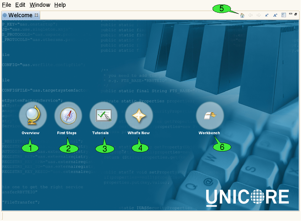
The welcome screen is composed of several web pages that are displayed in the internal web browser of the client:
-
The Overview page 1 contains links to parts of this document and the Eclipse framework’s user manual.
-
The First Steps page 2 helps in configuring the client for accessing different Grids.
-
The Tutorials page 3 offers links to Flash-based online tutorials that will be displayed in a web browser.
-
The What’s New page 4 summarizes the most important new features of the current client version and lists general UNICORE related news.
A navigation bar on top of each page contains hyperlinks to the other pages. The toolbar of the welcome screen can also be used to navigate back and forth between the pages 5. In order to leave the welcome screen and start working with the client, click the Workbench hyperlink 6. The welcome screen can later be re-opened via the Help → Welcome pull down menu item.
3.2. The Eclipse workbench
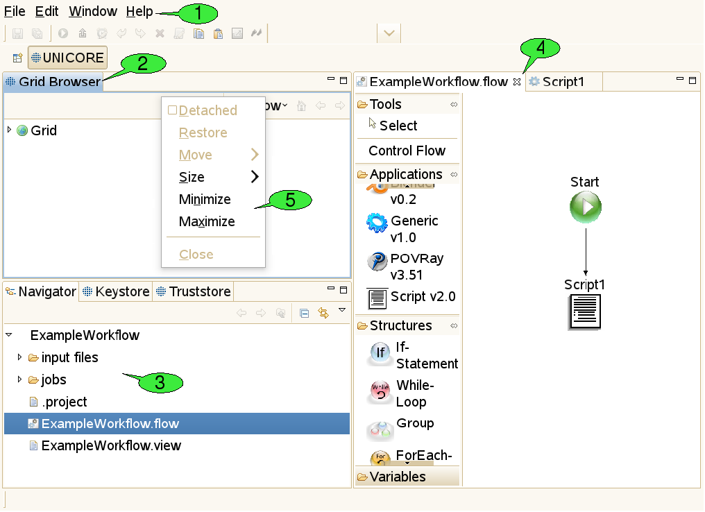
The client’s main window is called the workbench (see [FIGURE_WORKBENCH]). It has different components which can be opened, closed, resized, re-ordered and even detached from the main window.
3.2.1. Menu bar and tool bar
At the top of the workbench, there is a menu bar from which different pull down menus containing ‘global’ actions can be opened 1. For convenience, some actions are available via shortcuts from the tool bar just below the menu bar. The items in the tool bar can change depending on the selection of objects in the client, mirroring the fact that different actions can be performed on different objects.
3.2.2. Views
Resizeable and draggable tab panels containing buttons and other controls are an integral part of all Eclipse based clients. These panels are called views 2. Apart from being resized and moved, they can also be closed and re-opened. Detaching a view from the workbench will embed the view in its own window. Double-clicking its title will maximise it and double-clicking the title once more will restore its original size. Some views are ‘singletons’, so only one instance of the view can be opened, whereas other views can be opened multiple times, showing a different content in each instance.
3.2.3. The workspace
The workspace is a directory, usually located on the local hard drive 3. It is supposed to hold all relevant user data needed for the daily work with an Eclipse-based client. Inside the workspace, the user data is organised in subfolders, so-called projects. All files within a project should be thematically related. In the UNICORE Rich Client, each job description file (with the extension ‘.job') and each workflow description file (`.flow’ file) is stored in its own project, together with its input files. Having a separate project for each job or workflow has the following advantages:
-
Jobs and workflows can get complex. They may need a large number of input files that might be organised in their own directory structure. Mixing up multiple jobs or workflows in a single project can therefore lead to mixing up input and/or output files.
-
Eclipse has its own notion of importing and exporting projects. This provides a nice mechanism for exporting jobs and workflows (e.g. to a single zipped file that contains all necessary input data) and sharing it with co-workers. In the UNICORE Rich Client, job input files should be put into a directory called ‘input files’ inside the project. Relative paths can then be interpreted relative to this directory, which makes sharing of projects very easy.
Apart from the data that are relevant to the user, the workspace also contains metadata that are used in order to manage user preferences and store the state of the Eclipse workbench. In the Eclipse framework, there are different views for displaying the content of the workspace. The most widely used view is called the Navigator view. It represents the workspace as a file tree and is very similar to most graphical file browsers. It can be used for creating, renaming, copying, and deleting projects, files and directories. Projects can also be ‘closed’ if unneeded. This will hide their content from the Navigator view.
3.2.4. Editors
When a file is supposed to be opened (e.g. after double clicking it in the Navigator view, Eclipse tries to identify a suitable editor by looking at the file’s extension. If an associated editor can be found, it is invoked and will display the file content. For example, ‘.txt’ files invoke a text editor, the ‘.flow’ extension invokes the workflow editor 4. File types can also cause associated external applications to be started; for example, a web browser for ‘.html’ files. If the filetype is not supported, an error message is displayed. Associations between file types and editors are defined in the preference page that can be reached via Window → Preferences → General → Editors → File Associations.
3.2.5. Context menus
Many functions in the client are available via context menus 5. In order to open a context menu, right click an object or a view. The items available in the context menu are different, depending on the object on which the context menu was opened.
3.2.6. Perspectives
The outer appearance of the workbench is very flexible and can change a lot over time. The user benefits from being able to hide information he does not want to see at the moment and arrange the remaining components in a way that fits his needs best. However, less experienced users may have to search for information they accidentally hid in the first place. In order to deal with this problem, the Eclipse framework has introduced the notion of perspectives. A perspective is a well defined arrangement of views and editors in the workbench. In addition to determining which components are visible in which spots, it can also influence the actions that can be performed from the tool bar of the workbench. A given arrangement can be saved as a perspective for later re-use and a user can always restore the original appearance of a perspective by resetting the perspective.
3.3. Basic security configuration
3.3.1. How does encryption with X.509 certificates work?
Most security mechanisms on a UNICORE Grid are based on X.509 certificates. For each X.509 certificate, there is a pair of cryptographic keys, that fit each other. These keys can be used to encrypt and decrypt messages: whatever has been encrypted with one of the keys can only be decrypted with the other key - but the keys are not equal. This is why this type of encryption is called ‘asymmetric’. Such an asymmetric pair of keys can be used in a public key infrastructure (PKI): The trick is that one of the two keys, called the ‘public’ key is published and therefore open to everyone, whereas the other key - called the ‘private’ key - is kept secret by the owner of the key pair. In order to be able to keep the private key secret, it must be very difficult to reconstruct or guess the private key by looking at the public key.
Everyone can use the public key to encrypt messages that only the owner of the private key can read. And, equally important, the owner of the private key can prove that he owns the private key by encrypting a meaningful message with it: everyone can use the public key to decrypt the message and make sure that it is meaningful, but only the owner of the private key can produce the encrypted message. Asymmetric encryption can also be used for digitally signing documents. With a digital signature, a person can prove that he really is the author of a document, or that he approves the content of a document. The most common way of creating digital signatures comprises two steps: first, a checksum for the document to be signed is computed. The checksum is a relatively short sequence of characters (compared to the document). It is computed by applying a well-known checksum function that always generates the same checksum as long as the content of the document is unchanged. Second, the checksum is encrypted with a private key. The encrypted checksum is published together with the document and forms the digital signature. A reader of the document can use it for checking whether the document was changed. To this end, he applies the same checksum function to the document and compares the result to the checksum that he obtains by decrypting the digital signature (using the public key).
In order to obtain an X.509 certificate from a key pair, the public key is stored in a document, together with some information about the certificate’s owner-to-be (e.g. name, email address, organisation). This document is then digitally signed with the private key of a certificate authority (CA), which means that the CA approves the creation of the certificate. This process is called ‘issuing a certificate’. Everyone can use the CA’s public key to check, whether the certificate has been signed by the CA.
3.3.2. How does UNICORE use X.509 certificates?
With X.509 certificates, UNICORE ensures two things: First, each client or server on the Grid can attest that he is who he claims to be. He does so by presenting his certificate - which contains the public key - and providing evidence that he knows the private key belonging to this public key (by encrypting a previously defined message). Since private keys are kept secret, he must be the owner of the certificate. Second, the public key is used to encrypt messages that only the person knowing the private key (the owner of the certificate) can read. This way an encrypted communication channel between different actors on the Grid is established (by secretly sending a newly created key that can be used for both encryption and decryption of additional messages). The protocol defining the details of establishing the encrypted channel is called Transport Layer Security (TLS), a successor of the Secure Sockets Layer (SSL).
3.3.3. What does this mean to the user?
Before accessing a UNICORE based Grid, each user needs to obtain a valid X.509 certificate which is issued by one of the certificate authorities (CAs) that the UNICORE servers trust. The client presents this certificate to the server whenever he is asked for authentication. The server then checks whether it trusts the CA that issued the certificate. It does so by searching for the CA’s certificate in a so-called ‘truststore’ i.e. a file that contains a list of trusted CAs' certificates. If the CA’s certificate is found, it knows it can trust the client. Analogously, the client checks whether it trusts the server. If both checks are successful, a communication channel is created.
All private keys for certificates that the user may want to use on the Grid are stored in a special file called ‘keystore’. The keystore is encrypted and secured by a passphrase that the user has to remember. During first startup, the Rich Client can create a new keystore file. It is also possible to reuse an existing keystore file. For simplicity, there is only one file that contains both truststore and keystore, so the list of trusted CAs is written to the same encrypted file that holds the private keys.
3.3.4. The Truststore view
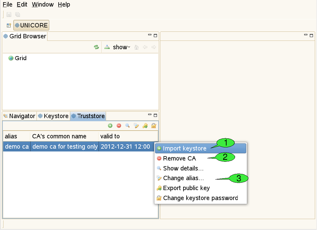
Use this view to add certificates of trusted certificate authorities (CAs) to the truststore (see [FIGURE_TRUSTSTORE_VIEW]). This is necessary in order to communicate with secure Grid services via an SSL encrypted channel. Failing to add the required certificates for the Grid infrastructure that you would like to use will result in errors when trying to contact any of the Grid services.
For each CA certificate contained in your keystore/truststore file, the truststore view displays the alias identifying the certificate (must be unique), the name of the CA, and the end of the certificate’s validity period. Please note that the current rich client version uses strict security rules and forbids the use of duplicate certificates in keystore/truststore. Therefore if you use an existing keystore from older versions, you have to remove the duplicate certificates.
In order to add trusted CA certificates, import a file containing these certificates (the file extension should be one of ‘.jks’, ‘.p12’, or ‘.pem’) 1. Certificates can also be removed from the truststore 2. Additional actions allow for opening a detailed certificate description, changing a certificate’s alias (used aliases must be unique) exporting public keys to ‘.pem’ files and setting the keystore password 3.
3.3.5. The Keystore view
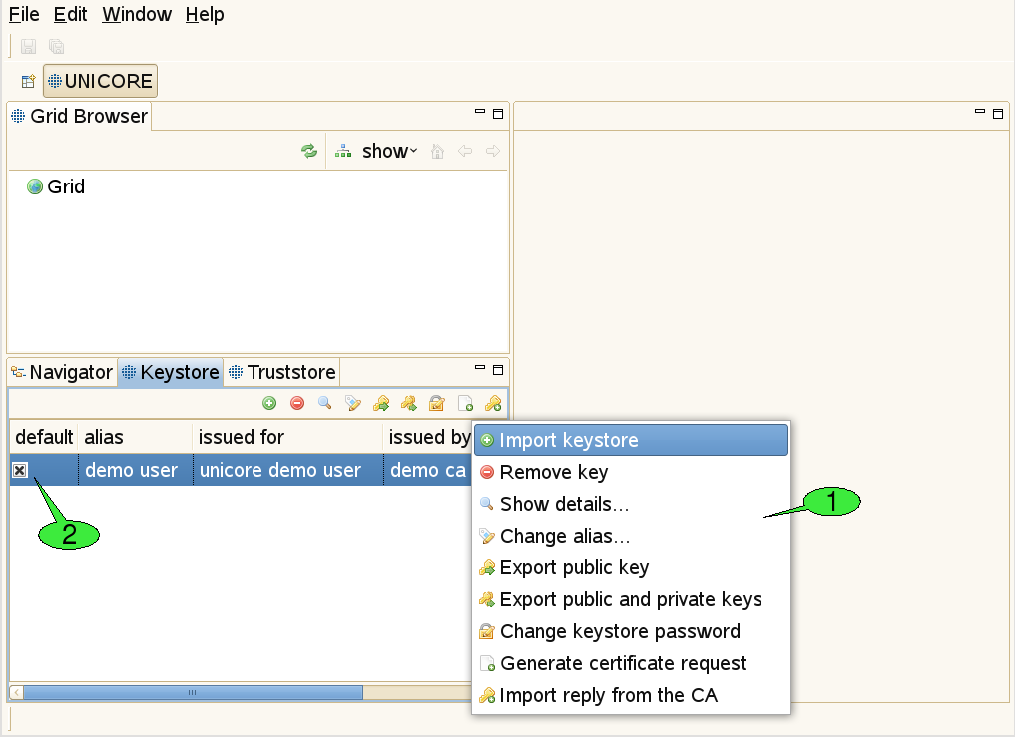
This view is used to manage private keys and the associated X.509 user certificates ([FIGURE_KEYSTORE_VIEW]). Different actions may be performed via the view’s context menu 1. The first item is used to import all private and public keys from an existing keystore file into the client’s keystore. The second item can permanently delete private keys from the client’s keystore. Additional items allow for displaying more details about a selected key, changing the alias that identifies the selected private key, exporting the certificate that belongs to the selected private key, exporting a number of private and public keys to an external keystore file and modifying the client keystore’s passphrase. In order to obtain a valid certificate from an existing CA, a certificate request can be created. For each request, a pair of private and public keys is generated. The private key is saved in the keystore. The certificate request must be sent to the administrator(s) of a CA. The response to such a request is usually a ‘.pem’ file, containing the certificate, now signed by the CA. By importing this file into the keystore (using the last item in the context menu), the private key associated to the certificate becomes functional. If the keystore contains multiple user certificates, a default certificate for accessing Grid services should be set 2. This default certificate can later be overridden by the Security Profiles view (see [SUBSUBSECTION_SECURITY_PROFILES_VIEW]).
3.4. Browsing and monitoring the Grid
3.4.1. The Grid Browser view
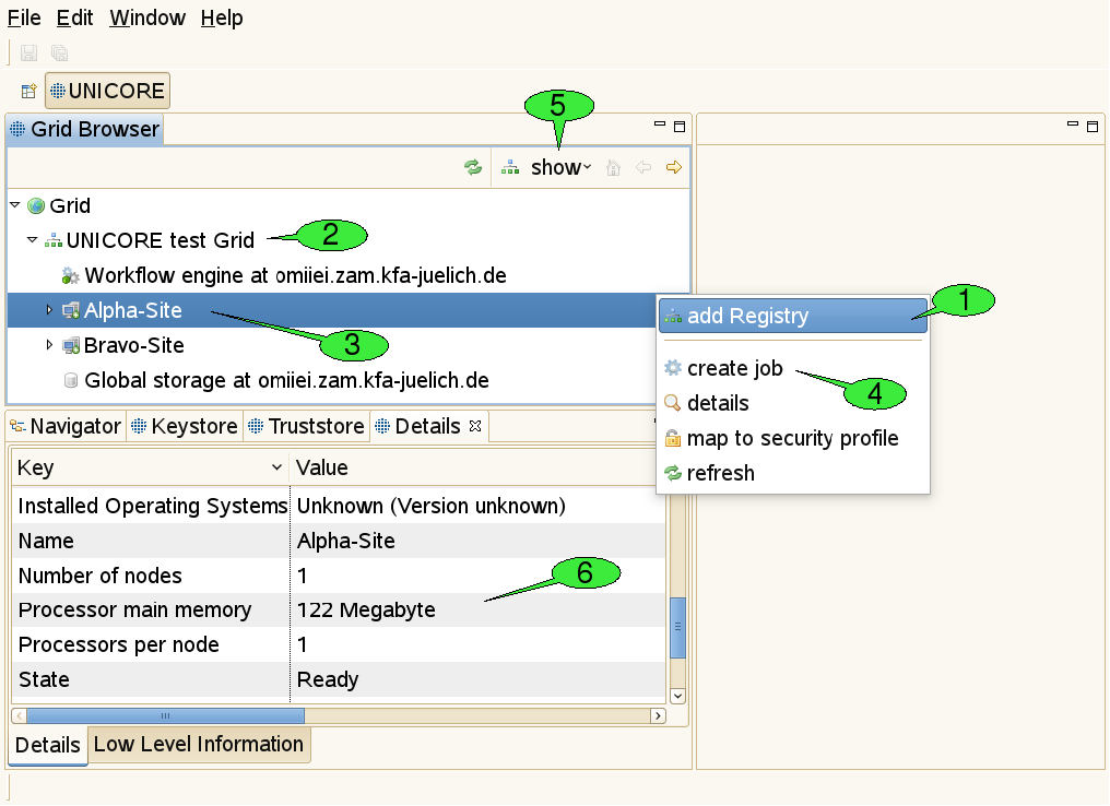
This view represents the Grid as a tree structure (see [FIGURE_GRIDBROWSER_VIEW], top left). The items that form the tree are called ‘nodes’ and represent Grid services and files.
There are numerous actions that can be performed on this view or its nodes:
-
Adding registries: For getting started, open the context menu (by right-clicking inside the Grid Browser) and select add Registry 1. In the appearing dialogue, enter the URL of a registry that serves as an entry point to the Grid: A registry is used for looking up all available services. For each added registry, a new node should appear just below the root node called Grid 2.
-
Refreshing nodes: By double-clicking a node, the represented Grid service is contacted and information about its state is gathered. This is called a refresh. After refreshing the registry, a new sub tree should open, displaying the target system and workflow services known by the registry 3. Target system services are used for job execution, workflow services are used for workflow execution.
-
Opening the context menu on a selected node: By right-clicking a node, a context menu that contains all available actions for the associated service will appear. For instance, users can create job descriptions for job submission to a target system by selecting the create job action from the target system’s context menu 4.
-
Filtering of Grid services: In large Grids, keeping an overview of the available services and finding relevant information might become difficult. In order to support the user with these tasks, configurable filters can be applied to the Grid Browser. Nodes that do not pass the set of active filters, will not be displayed to the user. The default filter shows job or workflow execution services and storages only. Services that are less frequently used can be revealed by using the show menu to the top of the Grid Browser view 5 and selecting All services. Additional filters allow to search for services of a specific type, display jobs and workflows that yield a particular state, or have been submitted within a given period of time. A file search filter can be used to retrieve all files that match a certain file name pattern.
-
Administrative actions: The Grid Browser offers additional actions like creating and destroying Grid service instances. These can be made accessible by increasing the detail level of the Grid Browser. To this end, select Window → Preferences from the menu bar. A new window will pop up, that can be used for specifying all sorts of preference settings (see [FIGURE_PREFERENCES_GENERAL]). User preferences are discussed in more depth in [SUBSECTION_PREFERENCES]. Grid specific settings can be made in the UNICORE category and its sub-categories. By setting the User Expertise Level to expert, the additional administrative actions become available (see [FIGURE_PREFERENCES_UNICORE]).
Although the Grid Browser displays the Grid as a tree, the actual topology of the Grid can only be modelled with a graph. The Grid Browser deals with this situation by depicting a single Grid service with multiple nodes. For instance, a job that is part of a workflow will be represented by two different nodes in the Grid Browser: one beneath the target system service that executed the job and the other one beneath the workflow management service that corresponds to the job’s parent workflow. These two nodes, however, share the same data model: whenever you refresh one of the nodes, the other one is being refreshed at the same time.
3.4.2. Grid Files
Remote files in UNICORE based Grids are accessible through UNICORE storages that can be searched directly in the Grid Browser. Directories and files are displayed as child nodes of the storage node. Double-clicking a directory will open it and list contained files and folders, while double-clicking a file will download that file to the local hard disk and open its content in an associated editor. Saving the file with the associated editor will also update the remote file’s content (except when the file is opened with an external editor). Data can be moved between different remote file systems. For instance, you can move a directory from one UNICORE storage to another with a single mouse drag. Files can also be uploaded to remote storages by dragging them from the workspace, a local file browser or the desktop. Due to a limitation of the Eclipse framework, files can only be downloaded to the workspace (via the Navigator view).
3.4.3. The Details view
When a node in the Grid Browser has been refreshed for the first time, information about the associated service is shown in the Details view 6. For target system services, this includes available resources like number of CPUs, amount of main memory, and a list of installed applications. For jobs and workflows, states and submission times are displayed, for Grid files, sizes and modification dates. Note, that this view is connected to the Grid Browser: Whenever a different node is selected, the Details view is being updated to display its details.
3.5. Job submission and visualisation of job outcomes
3.5.1. The Job editor
The UNICORE Rich Client offers graphical editors for setting up job descriptions. Instead of having to edit text-based job descriptions, the user is provided high level interfaces which are taylored to the applications he wants to execute on remote systems. The client is easily extensible with new application specific user interfaces as new applications are introduced to the Grid environment. Setting up a job description only requires a few simple steps and can be performed within a couple of seconds. The first step is the creation of a job project.
3.5.2. Creating a job project
There are different ways to create a new job project:
-
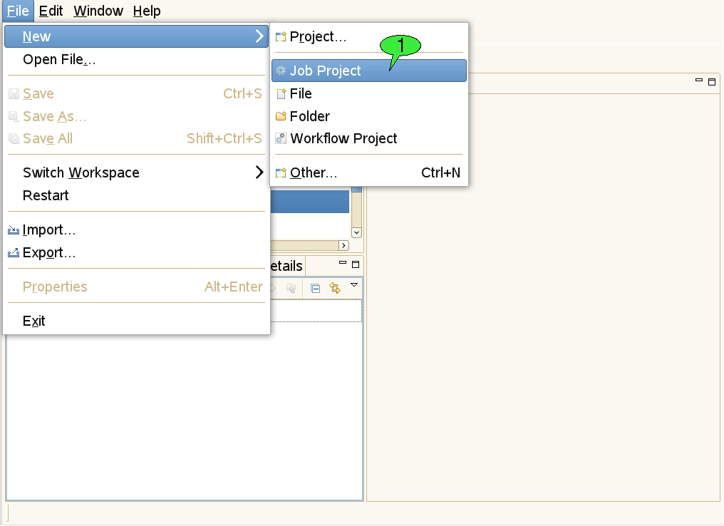
Select File → New → Job Project from the menu bar (see 1 in [FIGURE_CREATE_PROJECT]).
-
Open the context menu of the Navigator view and select New → Job Project.
-
Use the create job item from the context menu of a target system node.
-
Choose the restore Job description item from a job’s context menu in the Grid Browser.
The first three of these options will pop up a series of wizard dialogs which will guide the user through the creation of the job project (see [FIGURE_JOB_CREATION_WIZARD]).
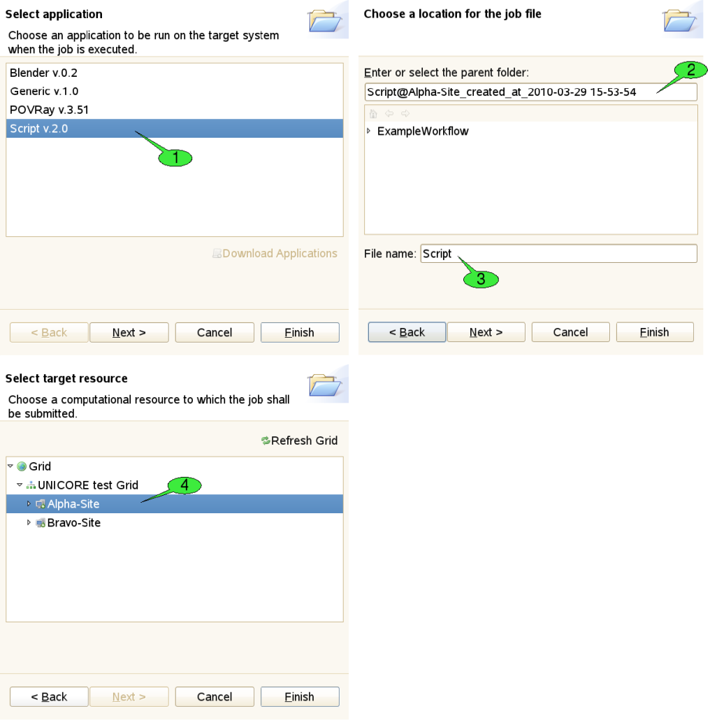
The first step of the wizard is used to choose an application to be run on the target system. In our example, we would like to execute a simple shell script. Therefore, we have selected the Script application 1. By pressing the Finish button the new job project is created. Click Next which will take you to the next wizard step. Here, a different name for the project 2 and the job file 3 can be set. The third wizard page allows for selecting a different target system for job submission 4. The selected target system can also be modified after the project has been created. When the job is created with the last option, both the target system selection and application to be run are restored from the server. Therefore, the job creation wizard shows the second wizard page, only (where you can set names for the project and job file).
3.5.3. Editing mode
The most convenient way to create a job project is using the context menu of a target system node (see 1 in [FIGURE_JOB_SUBMISSION]), as the corresponding target system will be pre-selected and the job creation wizard can be completed on the first page.
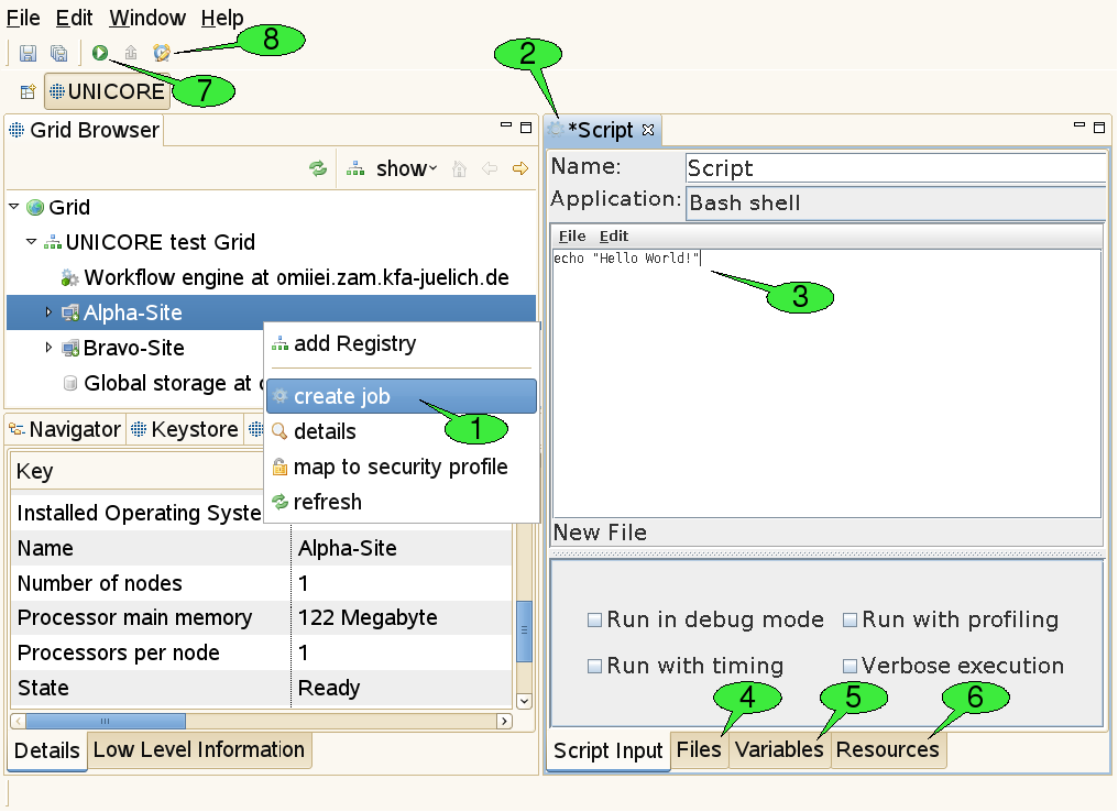
Once the job project and job file have been created, a new job editor will be opened in editing mode, displaying a graphical user interface (GUI) for the application 2. It allows for defining the input parameters of the job to be run. The GUI for the Script application provides an embedded text editor for typing in the shell script 3. New application GUIs can be installed by selecting Help → Software Updates → Download Grid Applications from the workbench’s menu bar. This option requires an application GUI server to be available on the Grid (if no server has been found, the option is not available). The job editor holds several tabs. First the application specific tabs are shown for setting parameters in a user friendly way.
In addition, the editor holds three generic panels:
-
The Files panel 4: This panel can be used to define file imports from remote locations or preceding activities in a workflow. The application specific panels usually only allow for defining imports from the local file system. File exports to remote locations can also be set up here.
-
The Variables panel 5: This panel can be used to set the application’s input parameters directly (circumventing the application specific panels that usually operate on these parameters, too. All parameters are passed to the application via environment variables. Furthermore, the panel allows for setting up additional environment variables for your application run.
-
The Resources panel 6: This panel can be used for specifying resource requirements of the job, like the number of CPUs needed for a calculation or the amount of memory. Furthermore, scheduled start time of jobs can be specified (i.e. set the time when job is submitted to the batch system). If user requires to run an application that uses a different execution mode (e.g. parallel execution), the option execution environment can be activated. For more information please read http://sourceforge.net/apps/mediawiki/unicore/index.php?title=ExecutionEnvironment. The tree-like view on the Grid to the right serves for changing the selected target system for job execution. Note that the list of suitable target systems is updated when changing resource requirements. Also note that the boundaries for resource requirements change when a different target system is selected. The selection can be undone by choosing a node that is not a computational resource (e.g. the Grid node or a registry node).
When all parameters are set, click the green submit button (see 7 in [FIGURE_JOB_SUBMISSION]) to submit the job to the selected target system.
An additional action in the tool bar of the job editor is used to set the job’s lifetime 8. When the job has reached the end of its lifetime, the job resource representing the submitted job is destroyed and its working directory is cleaned up automatically. This implies that the job’s outcomes cannot be accessed hereafter. The default lifetime for jobs is set to 720 hours (30 days).
3.5.4. Monitoring Mode
As soon as a job is being submitted, the job file is copied into a newly created subfolder of the ‘submitted’ folder in the job project. The subfolder’s name consists of the String ‘submitted at’, followed by a timestamp, e.g. ‘2010-03-29 16-00-34’ that indicates when the job was submitted (1 in [FIGURE_JOB_OUTCOMES]). This way, a history of all submitted versions of the job is kept and the user can later look up old job descriptions and compare the results of the associated job executions. The copied version of the job file is then opened in a new job editor.
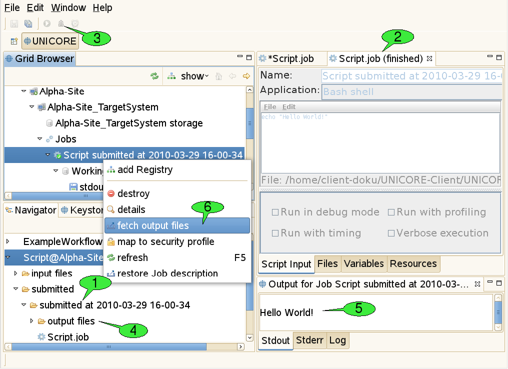
In order to inform the user about the execution state of the job, the editor is put into monitoring mode. This means that the job description cannot be edited anymore and the title of the job editor indicates the current execution status 2. The status may be one of the four values submitting, running, finished, and failed. If the job editor is closed in state submitting the job submission cannot be performed successfully and the subfolder with the copy of the job file is deleted automatically. If the editor is closed in state’running', execution of the job will continue normally on the server side. By double-clicking the job file copy in the Navigator view, the job editor will be re-opened in monitoring mode and continue to watch the job execution. Jobs can be aborted by selecting the ‘abort’ item in their context menu. Aborting a job will interrupt the execution of the associated application as soon as possible (this depends on the target system’s ability to abort application runs), but leave the job node (and its working directory node) accessible in the Grid Browser. In contrast, destroying a job will first abort the job and then clean up all used resources including the job’s working directory.
3.5.5. Fetching Job Outcomes
Once the job has finished successfully, the fetch output files action becomes available in the tool bar of the job editor in monitoring mode 3. After clicking it, a dialog will appear that shows all produced output files and allows you to deselect files you do not want to download. After clicking OK the selected files are downloaded to the ‘output files’ directory in the subfolder that contains the copy of the submitted job 4. Finally, a new application specific Job Outcome view will appear showing the contents of the job’s output files 5. In our example a simple text editor shows the output of the script, but more advanced visualisation software is used for displaying the results of scientific applications (e.g. 3D molecule visualisations for chemical applications). Alternatively, job outcomes can be fetched by selecting fetch output files from the context menu of job nodes in the Grid Browser view 6.
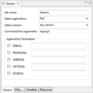
3.5.6. Generic application
The Generic application automatically builds application specific graphical user interfaces (GUI) based on metadata configured in the IDB of the UNICORE/X. The GUI allows a user to select any application defined in a server’s IDB for execution. Depending on the selected application it is possible to select a version, to insert command line arguments and to choose other application parameters. Further information can be found in the UNICORE/X manual.
3.6. The Workflow editor
This software component provides a graphical editing tool for workflows, offering features like copy & paste, undoing changes, performing automatic graph layouts, zooming, and printing of diagrams. Each workflow is created in its own project and can be submitted and monitored like a single job.
3.6.1. Creating a workflow project
In order to create a new workflow project, either select File → New → Workflow Project from the workbench’s menu bar or select New → Workflow Project from the context menu of the Navigator view (see [FIGURE_CREATE_PROJECT]). After providing a valid name for both the parent folder and the workflow file, the project is created.
3.6.2. Editing mode
When creating a new workflow project or opening an existing workflow file, a new workflow editor instance is opened for setting up the workflow description (see [FIGURE_WFEDITOR_EDITING]).
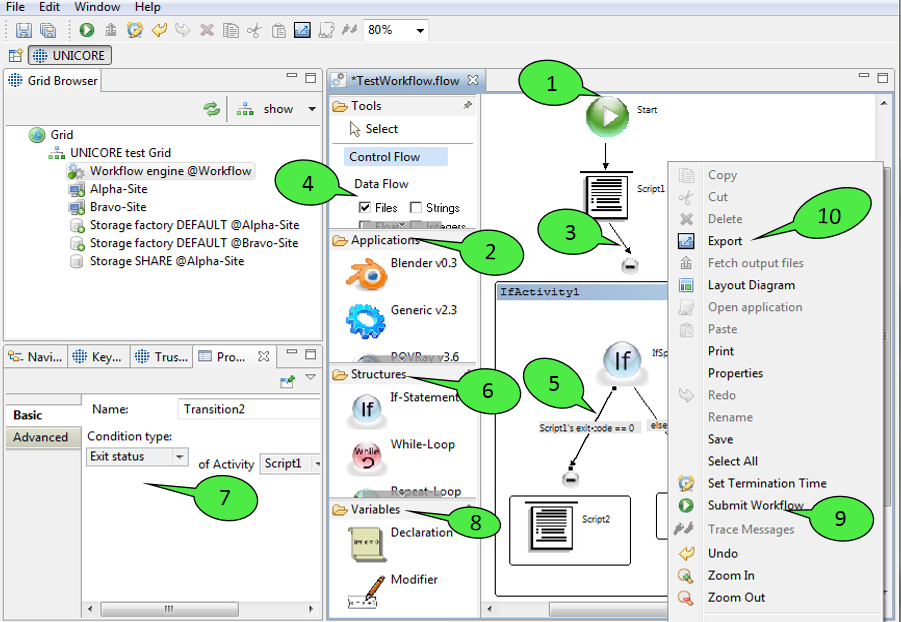
Workflow descriptions are graphs consisting of nodes (commonly called activities in workflow terminology) and edges (called transitions). When a workflow diagram is created, it only displays a single activity: the starting activity of the workflow 1. Execution of the workflow begins at this activity. In order to add new elements to the workflow, select them from the palette on the left hand side and click in the diagram where you want to place them. Currently, the palette offers the following elements that can be added to the workflow:
-
Application activities
These activities represent jobs that are submitted to target systems during workflow execution in order to run specific applications there. For each application GUI that is installed in the client platform, the palette shows a small icon and the name of the application 2. By selecting an icon and left-clicking a free spot within the workflow editor, a new activity for the associated application will be created. This leads to the creation of a job file in the ‘jobs’ directory of the workflow project as soon as the workflow is saved. When being double-clicked, application activities will open the job editor for the associated job file. The editor can be used in order to change the job description. When a job is embedded in a workflow, there are a several additional possiblities for specifying the job’s inputs and outputs that are not available for single jobs:-
Additions to the Files panel: A File can now be exported as a Workflow file meaning that the file will be stored on some global storage and will be available to subsequent workflow activities.
-
Additions to the Variables panel: This panel can be used to set the application’s input parameters to the values of workflow variables. Workflow variables can be declared by special activities and modified while the workflow is executed. Their current value during workflow execution is maintained by the workflow engine and may be fed into a job’s description before the job is submitted. This mechanism allows for running the same job multiple times, with different parameter values e.g. for performing parameter sweeps.
-
Additions to the Resources panel: Workflow jobs do not require users to select a single target system for job execution. This is due to the fact that the workflow engine has a resource broker which is capable of distributing jobs to suitable target systems. In this process, specified resource requirements of the job (e.g. amount of memory) are compared to the target systems' offerings for finding a computing resource that fulfils the requirements. This is generally referred to as ‘match-making’. In order to narrow down the choice of target systems used for match-making, the user may select one or more target systems as ‘candidate resources’ for the job. Again, the selection can be undone by choosing a node that is not a computational resource (e.g. the Grid node or a registry node).
-
-
Transitions
Transitions represent the flow of control that passes from one activity to the next. Currently, there are two types of transitions: unconditional 3 and conditional 5 ones. Only unconditional transitions can be added to the workflow manually. Conditional transitions are used in If-statements and While-loops and are added automatically. The reason for this is that conditional transitions may require a different joining behaviour: the default joining behaviour when an activity has multiple incoming transitions is called ‘synchronisation’. This means that the activity is only processed when all incoming transitions have been processed. As you might imagine, this behaviour is no longer appropriate when conditional transitions are used: the activity that joins the if and else branches of an If-statement would never be processed if it waited for both branches to finish. In order to hide this complexity from users that are unfamiliar with workflow processing and programming languages, If-statements and similar constructs will be modelled as sub-workflows that automatically define the appropriate joining behaviour.-
In addition to the Control Flow view Data Flow view can also be selected to visualize the input and output of created workflow jobs. You can check option Files 4 to have a graphical view of the input and output files of the activities. Moreover the output of one job can be used by other jobs by simply connecting (drag and drop) it to the respective input files of other jobs. You can check various workflow variable types (Strings, Float and Integer) to visualize the input parameters of the workflow jobs.
-
-
Workflow structures
Workflow structures are subgraphs that bring their own semantics on how to process their child nodes. Currently, five workflow structures are provided: groups, If-statements, Hold-activities, While-loops, and ForEach-Loops 6.-
Groups are the simplest of all subgraphs. They are just containers for other activities. Their content may be hidden by clicking the small minus symbol at their top.
-
If-statements influence the flow of control and contain two additional subgraphs (which are modelled as groups): the if-branch and the else-branch. The if-branch is processed when a certain user-defined condition holds. If the condition evaluates to false the else-branch is processed instead. Both branches can contain arbitrary activities and transitions, thus permitting nesting of workflow structures. Conditions can be altered by double clicking the conditional transition. This will open up the Properties view which displays relevant properties of workflow elements 7. Most properties can be modified through this view. There are currently four types of conditions: the first type compares the exit status of an application to a value provided by the user, the second one tests whether an output file with a given name has been created by an application activity, the third one compares the value of a workflow variable to a given value, and the last one checks whether the current time lies before or after a given point in time.
-
The Hold-activity is very simple. After any workflow structure, a hold structure can be placed to hold the workflow. When a workflow is submitted to the workflow engine and hold operation gets executed, the workflow engine waits for user input to continue. The held workflow can be continued by right clicking on it in Grid browser and selecting resume option.
-
The While-loop provides a single subgraph called the loop-body that can be processed multiple times (as long as the loop’s condition holds true). The While-loop declares a workflow variable that reflects the current number of loop iterations, the so-called loop ‘iterator’. It also declares a variable modifier that increments the loop iterator. The variable declaration can be changed in the Properties view of the red activity at the top of the loop and the variable modifier can be set up in the Properties view of the associated modifier activity (at the bottom of the while-loop). Please note that in the properties view only the rename button is activated, as the other buttons add and remove do not make sense in case of a while-loop/repeat-until-loop.
-
The Repeat-Until-loop works just like the while loop, but its loop-body is always processed once before the condition is evaluated for the first time. Also, compared to the while-loop, the condition is negated, i.e. the loop ends when the condition becomes true.
-
ForEach-loops can be used in order to create many similar jobs without having to set up each job individually. They have two different modes of operation. The first mode will iterate over a set of workflow variable values and run the job(s) contained in the loop body once for each value in the set. The workflow variable values can be used as input parameters for these jobs. Complex parameter sweeps are possible, as multiple workflow variables can be sweeped at the same time. The second mode is used to iterate over a set of files. The file set may consist of any combination of local, remote or workflow files. This mode provides a convenient way to process many different files simultaneously. The operational mode and the parameters to the selected mode can be modified in the Properties view of the orange activity at the top of the ForEach-loop. The iterations of the ForEach-loop are usually executed in parallel. However, there is an upper bound of parallel iterations which results from the workflow engine’s capabilities. There is also a way to lower this boundary by providing an Integer value for the Number of parallel tasks in the Properties view of the ForEach activity. Setting this value to ‘1’ will lead to sequential execution of the loop iterations.
-
-
Variable declarations and modifiers 8
Additional workflow variables can be declared using the appropriate Declaration activity. The Properties view of this activity allows for (re-)naming the variable and assigning it a type (e.g. String or Integer) and initial value. A Modifier activity can be used to change the value of a workflow variable later.
When the user is pleased with the workflow description, the workflow can be submitted via the editor’s context menu 9 or the workbench’s tool bar. It can also be exported to an XML based workflow language that the workflow engine understands 10. The exported workflow can later be submitted to the workflow engine by the UNICORE commandline client. This feature is useful e.g. in order to make predefined workflows available via a web interface (the Chemomentum web portal solution uses the commandline client for workflow submission).
3.6.3. Monitoring mode
The workflow editor is also used for monitoring the execution of workflows, so the basic graphical representation of a workflow stays the same before and after submission to the workflow engine (see [FIGURE_WFEDITOR_MONITORING]). This helps in identifying which part of the workflow is being executed at a given point in time.
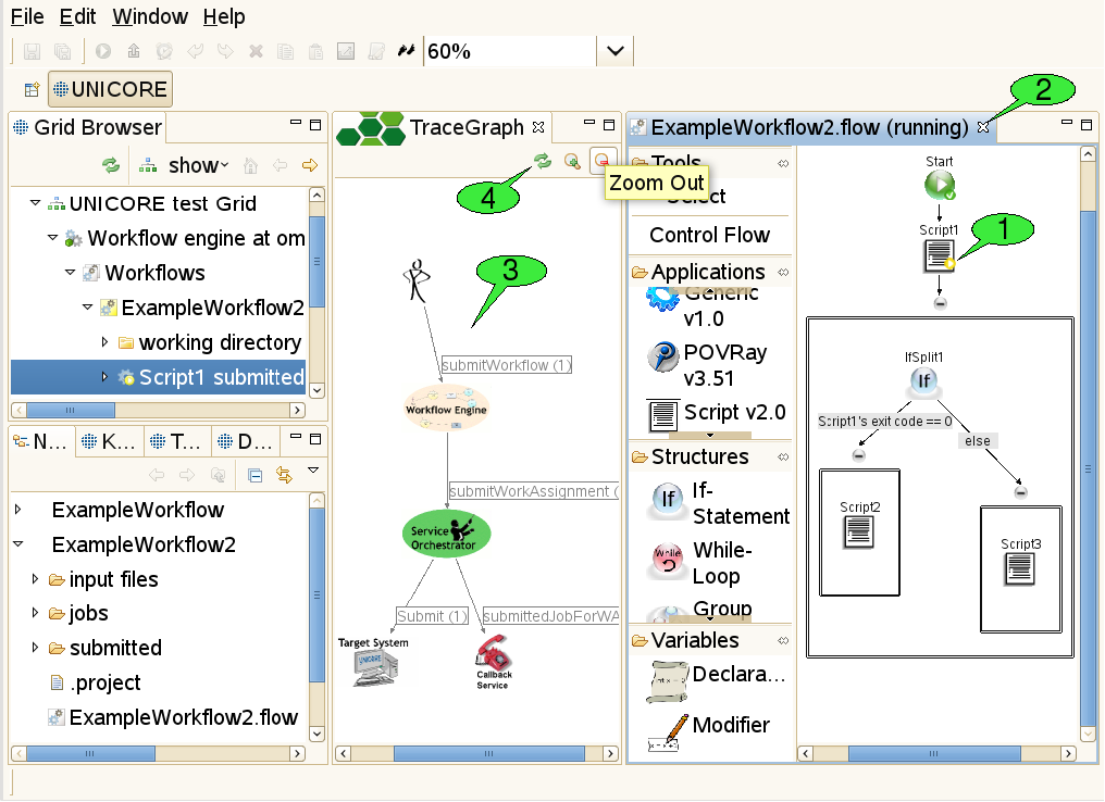
When a workflow has been submitted, a new folder is created in the ‘submitted’ subfolder of the workflow project. This folder contains a copy of the workflow file that is automatically opened in a new workflow editor panel - in monitoring mode. In this mode, the editor disallows any changes to the workflow. It displays the progress of workflow execution by adding small icons to the nodes of the workflow graph that symbolise the execution state of these parts 1.
Outcomes of jobs can be fetched as soon as the jobs have finished. This function is available via the context menu of application activities and the fetch output files action in the global tool bar (after selecting the activity for which to fetch outcomes). Job outcomes are downloaded to the ‘output files’ folder again, so they can easily be found later and associated with the workflow by which they were produced. Monitoring a workflow can be interrupted by simply closing the editor panel 2. By double-clicking the file that represents the submitted workflow (in the Navigator view), the editor panel will be re-opened and continue to monitor the execution of the workflow.
3.6.4. The Trace Graph view
In addition to monitoring the execution states of activities in the workflow, the user may trace the workflow for finding out where his jobs were submitted. This action is available via the context menu of the workflow editor. A trace graph will open, showing all messages that were sent by the workflow system during the execution of the workflow 3. By hovering the mouse over a node or edge in the trace graph, additional information about the element is displayed in a tooltip. The set of traced messages can be updated by clicking the Refresh button in the tool bar of the Trace Graph view 4. Additional buttons allow to zoom in and out (zooming can also be achieved by rotating the mouse wheel while pressing the ‘control’ key).
3.7. Interactive site access
The UNICORE Rich Client features a Terminal view which can be used to log on to remote hosts via SSH and GSISSH. It complies to the VT100 standard for terminal emulation and can hold multiple terminal sessions (in multiple tabs). Sessions can be created via the open terminal action from the context menu of a target system node. Please note, that this action is only available, if the administrator of the UNICORE site has enabled interactive access and provided necessary information about the target system, i.e. the host name and port that should be used for establishing the interactive connection and the available connection methods. Currently, the UNICORE Rich Client provides two different secure connection methods, Plain SSH and GSISSH. Apart from that, additional protocols can be used in the future — both UNICORE client and server are extensible in this regard.
3.7.1. Plain SSH
When connecting to an SSH server via plain (i.e. conventional) SSH, the user can choose between three different authentication methods :
-
Password
-
Keyboard-Interactive
-
Public-key: If the user’s private key path wasn’t specified before, the UNICORE Rich Client tries to find the key in the appropriate default directory (e.g. ~/.ssh/id_dsa). If this fails the user is prompted to specify the path. In case your private key format is not recognized properly, please read [SUBSUBSECTION_INVALID_KEY_FOR_SSH].
3.7.2. GSISSH
The GSISSH connection method provides access to GSISSH servers via RFC-3820 compliant proxy certificates. The proxy is created from the keystore of the UNICORE Client when the user starts to connect to the server. It can be stored on the local machine if required. It is possible to choose between different aliases representing different keys in the keystore, different delegation types, and different proxy types. Furthermore, the lifetime of the proxy certificate can be set (the default is 12 hours). When connecting to GSISSH servers the UNICORE Rich Client converts the PEM formatted CA certificates in the UNICORE client’s truststore to GSISSH-conform certificates, and stores them on the local machine. By default these files are created in the ~/.globus/certificates folder. However, this can be changed in the client’s preferences at UNICORE → Terminal→ GSISSH.
3.7.3. How to open a terminal
There are different ways to open a terminal shell for a target site. The most convenient method is to right click a UNICORE target site in the Grid Browser view and select the Open Terminal menu item (see 1 in [FIGURE_OPEN_TERMINAL]).
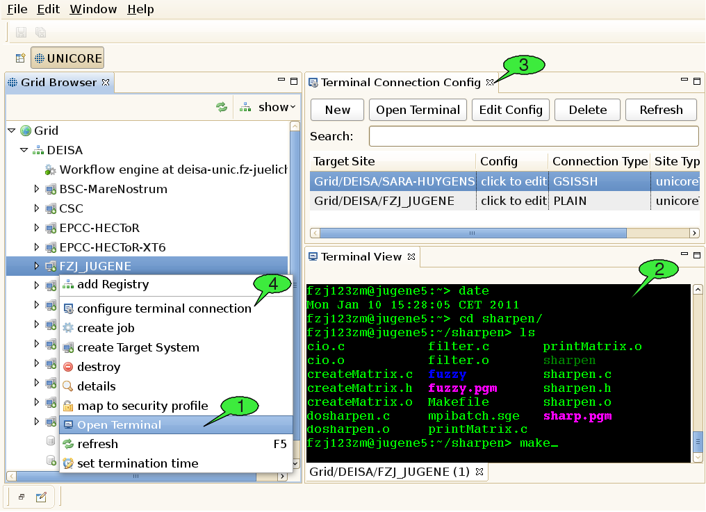
If the user connects to a site for the first time, he will be prompted to choose one of the available connection methods, in case the administrator of the UNICORE site has provided the necessary information in the IDB. If no connection information is provided, the user can enter the hostname, port, and login name manually. When all required connection data has been gathered, the secure connection process is triggered and the terminal view should show up automatically (see 2 in [FIGURE_OPEN_TERMINAL]). Alternatively, the user can open terminal shells by using the Terminal Config view.
3.7.4. How to maintain and configure connection information
A second view, the so-called Terminal Connection Config view (see 3 in [FIGURE_OPEN_TERMINAL]), can be used for modifying the user’s settings for interactive access to different target systems. The Terminal Config View can be invoked by selecting the configure terminal connection menu item (see 4 in [FIGURE_OPEN_TERMINAL]) from the context menu of a target site in the Grid Browser.
The view provides a table with all SSH target sites that have previously been invoked by the user. The user can rename the target site, or set a default connection type in the table. To edit the site’s terminal configuration the Config column or the Edit-button in the top menu can be clicked. This action will open a dialog for editing the parameters of different connection methods. The values are stored permanently in the UNICORE client after clicking Ok.
Custom target sites can be created by clicking the New button in the top menu. Terminals to such sites can only be opened from the Terminal Config view. They can be recognised by the CustomTargetSite tag in the Site Type column.
4. Advanced Usage Scenarios
4.1. File sets and file names with wildcards
When staging in files from UNICORE storages, iterating over filesets with a ForEach-Loop or transferring files between workflow tasks, the asterisk (*) wildcard can be used for matching multiple files in a specific folder. For instance, in the Files panel of the job editor, specifying an export with the value *.png in the File(s) in Job Directory column tells the client to stage out all files with the ".png" extension. In general, an * matches any sequence of characters in file names. Wildcards can also be used to complete directory names, so the pattern output_dir*/std* would tell the client to stage out all files starting with std that are located in sub-directories of the job working dir starting with output_dir. As you can imagine, this is very valuable when dealing with large file sets.
However, the introduction of this mechanism poses one challenge: how can the user specify how multiple matched files should be named in the job working directory when being imported? Imagine there are two jobs within a workflow, job1 (maybe a rendering application) exports a set of files using the pattern *.png, whereas job2 (an application that can merge multiple .png files into a video) imports all these files from the first job. By default, when importing wildcarded files from job1, the client just uses the original pattern (in this case *.png) as a file name pattern for the import declaration inside job2. This means that the transferred files should retain their original names (as in the working directory of job1).
Now, since version 6.4.3, the UNICORE Rich Client allows you to modify the wildcarded file name pattern for file imports. A common reason for this would be that the application executed by job2 expects the files to be named following a particular pattern. Let’s assume that this application identifies incoming .png files by the prefix input, i.e. it looks for all files in the job working dir starting with input and processes them. In this case, you can force the imported files to start with the prefix input by changing the default file name pattern for the import from *.png to input*.png. This leads to simply prepending input to the original file names.
At this point, it is important to understand that the UNICORE workflow engine identifies the wildcards (*) in both export patterns (*.png as defined by job1) and import patterns (input*.png) and tries to align them. As a result, it will replace a wildcard in the import pattern with those parts of the file names that have matched the corresponding wildcard in the export pattern of a previous job. We will come back to this later.
Let’s assume for a moment, that the files produced by job1 are called output01.png, …, output99.png. With the patterns above, this would lead to the files being called inputoutput01.png, …, inputoutput99.png, which looks ugly (although functionally it probably doesn’t make a difference). If you would like to change this, you should change the export pattern of job1 to output*.png. This leads to a situation where the workflow engine only matches the continuous numbers (01-99) against the wildcard in the export pattern. Thus, after aligning export and import pattern, it would rename the files to input01.png, …, input99.png inside the working directory of job2.
But what happens if job1 produces a whole structure of numbered (or otherwise unique) directories and output files and you would like to import that structure into job2 (and maybe change some of the directory names, or merge parts of the directory structure)? Fear not as this is supported as well!
For this to work, you can use one of the following two approaches:
-
Export and Import patterns have matching wildcard positions
-
Import patterns use group variables ${1}, …, ${n} representing matched wildcards in the export patterns
An example for the first approach would be the pattern outputs/iteration*/doc* for declaring the exports of job1 and the pattern inputfolder/input* for declaring the imports of job2. Let’s assume that job1 produces folders named outputs/iteration_a, …, outputs/iteration_z, each of which containing two files named doc.pdf and doc.ps. The UNICORE workflow engine would try to align these patterns in a way that it understands which asterisk in the import pattern matches which asterisk in the output pattern. In order to do this, it compares the patterns to each other, starting with the LAST path segment (i.e. the file name), making its way to the beginning of the patterns segment after segment.
That means that it compares the file names (doc* and input*) first and notices, that both contain a wildcard, so it assumes that the characters represented by these wildcards should be the same. Thus, the two imported files will be named input.pdf and input.ps for each iteration. It then continues to compare the next segments of the patterns, in this case iteration* and inputfolder. Since inputfolder does NOT contain a wildcard, all imported files will be merged into a single folder. If the segment read inputfolder* instead, the original directory structure would be retained, but the directories would be named differently, i.e. inputfolder_a, …, inputfolder_z. Note, that comparison of the two patterns stops, as soon as one of the two patterns ends, which allows for cutting off or prepending parent dirs.
While this first approach is already quite flexible, it doesn’t cover all possible use cases. In order to handle even more demanding situations, the second approach was introduced. Let’s stick to our previous example, but assume that files have to be put directly in the job working directory and should be named doc_a.pdf, doc_a.ps, …, doc_z.pdf, doc_z.ps.
How can you achieve this with the first approach? You can’t! Instead, you would provide an import pattern with group variables, in this case doc${1}${2}. The workflow engine would recognize the variables and replace all occurences of ${1} with the characters that were matched by the first wildcard in the export pattern and all occurences of ${2} with the characters that were matched by the second wildcard. You can easily imagine that this allows for lot of flexibility in terms of renaming/restructoring imported directories and files.
5. Troubleshooting
5.1. Event Dialogs and the Client Log
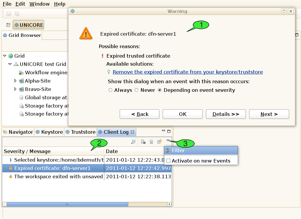
Using the software, errors or other noteworthy events may occur. The UNICORE client offers an elaborate mechanism for logging events as well as identifying and fixing runtime errors. Occuring events have a severity level that can be any of Error, Warning, or Info. By default, errors and warnings lead to opening an event dialog providing a brief problem description (see 1 in [FIGURE_TROUBLESHOOTING]), whereas events with the Info severity level are just logged to a file silently.
When the cause of the problem has been clearly identified, the event dialog may also offer a list of available solutions for the problem. There are two different types of solutions: plain text explanations helping the user in understanding and fixing the problem himself and dynamic links that trigger certain actions to fix the problem automatically. In case a problem was clearly caused by an error in the client’s program code, the software helps the user to fill in a problem report and send it to the unicore-problem-reports@lists.sourceforge.net mailing list. When encountering additional errors that look like bugs, feel free to compose a mail to this mailing list, too. This will help us improve the sofware quality. Please remember to attach the stack trace that can be viewed when clicking the Details button inside the event dialog. Additional controls in the dialog let the user choose whether to pop up the event dialog in case additional problems with the same cause arise. This only works when a problem’s cause has been identified. All events are written to a log file, enabling the client to list them in the Client Log view (see 2). The event list can be sorted according to the event message or the timestamp that is attached to each event.
Events can be viewed by double clicking them inside the list. This will open the event dialog once again for displaying the selected event. The Back and Next buttons can be used to navigate through the event list. The Client Log view can also be used to configure event logging and the event dialog’s pop-up behaviour. To this end, open its pull-down menu and select the Filter item (see 3).
5.2. Common Problems
5.2.1. Frequent connection timeouts and other network related problems
The UNICORE middleware heavily relies on network communication via the Hypertext Transfer Protocol (HTTP). HTTP is also used for surfing the world wide web, so when you are able to browse web sites from your client machine, you should be able to contact well-maintained UNICORE Grids, too. Similarly to web browsing, you might run into trouble when you are behind a proxy server. Additional problems may occur in very slow network environments, where you might experience frequent connection timeouts. In both scenarios, you should check the client’s network preferences (see [SUBSUBSECTION_PREFERENCES_GENERAL]).
5.2.2. Services disappear from the Grid Browser after a refresh
When trying to refresh the client’s information about a Grid service that you are not allowed to access with your user certificate, the service node in the Grid Browser will change its appearance. Depending on the preferences of the Grid Browser, inaccessible or failed nodes may also be hidden from the Grid browser (see [SUBSUBSECTION_PREFERENCES_GRID_BROWSER]).
5.2.3. Outdated view of the Grid
In order to minimize network traffic, the UNICORE Rich Client caches quite a bit of information about Grid services it finds. This also helps improve the performance in many situations. However, it might lead to situations where the client shows an outdated view of the Grid (e.g. it displays files that have already been deleted by someone else on the server). Often, a manual refresh on the affected services or their parent services will help (usually invoked by double-clicking a service; note: double-clicking files will lead to downloading them to a temporary folder, instead double-click their parent folder).
5.2.4. Problems with the internal Web Browser
Eclipse provides an internal Web browser that can be used for displaying HTML content within the Rich Client. Note, that the client’s welcome screen relies on this browser implementation, too. On GTK Linux machines, the internal web browser is based on the xulrunner library, thus absence of the xulrunner library can mess up the welcome screen and make the internal Web browser unavailable. This might be fixed by installing the xulrunner library, e.g. on an Ubuntu system type "sudo apt-get install xulrunner".
5.2.5. Problems with the Unity desktop
On Ubuntu, main menus may be hidden when using the Unity desktop (see Eclipse bug 330563). A workaround seems to be to set the UBUNTU_MENUPROXY environment variable to 0 before starting the client, e.g. by "export UBUNTU_MENUPROXY=0".
5.2.6. Unsupported key format for interactive site access via SSH
When using a private/public key pair that was created with proprietary Windows tools e.g. F-Secure, or Secure Shell Client (SSH.com), you might get an error message when trying to open a terminal. The URC SSH plugin is not able to process such proprietary private key formats. However, it is possible to convert the format of your existing private key to OpenSSH format, which can be handled by the URC. To achieve this you can use the free Third Party Software PuTTYGen:
-
Download the Windows application PuttyGen.exe (puttygen.exe). Alternatively, you can download the whole Putty software (putty-x.xx.installer.exe) from http://www.chiark.greenend.org.uk/~sgtatham/putty/download.html
-
Execute PuttyGen (e.g. double-click puttygen.exe)
-
Click the load button in the Putty Key Generator window to load your existing private key. Please remember to select All Files (".") from the file filter in the file browser. By default the PuTTY Private Key file extension (.ppk) is set. Open the private key file which you want to use in the UNICORE Rich Client.
-
Enter the passphrase of your private key. You should see some information about the loaded private key and the associated public key in the panel of the PuTTY window.
-
To create a copy of your private key in OpenSSH format, go to the Conversions menu and select Export OpenSSH key.
-
Save the newly created private key in OpenSSH format.
-
Edit the private key in the Terminal Config view and select the newly created OpenSSH key. You should now be able to authenticate to the desired target system given your public key has already been placed there before (there is no need to exchange the public key). Restart the URC if the private key used before is still cached in the system and open a shell to the target system.
6. Reference
6.1. A brief history of UNICORE
The UNICORE (Uniform Interface to Computing Resources) system was originally conceived in 1997 to enable German supercomputer centres to provide their users with a seamless, secure, and intuitive access to the heterogeneous computing resources at the centres. As a result, the projects UNICORE and UNICORE Plus were funded by BMBF, the German Ministry for Education and Research, with the following objectives:
UNICORE was designed to hide the seams resulting from different hardware architectures, vendor specific operating systems, incompatible resource management systems, and different application environments. Retaining organisational and administrative autonomy of the participating centres was a key objective of UNICORE. None of the service providers should be forced to change historically grown computer centre practices, naming conventions, and security policies to be able to use the full benefits of UNICORE. Security was built into the design of UNICORE from the start relying on the X.509 standard. Certificates are used to authenticate servers, software, and users as well as to encrypt the communication over the open internet. Finally, UNICORE had to be usable by scientists and engineers without having to study vendor or site-specific documentation.
Version 6 is a major milestone in the continuous development of the proven Grid software. It retains the rich functionality of previous versions, like seamless access to heterogeneous resources, complex workflows, and secure computing in a Grid environment. Application level brokering has been added to meet user requirements. The graphical user interface has been improved for greater efficiency and ease of use. Some user actions that turned out to be redundant were consequently removed. In addition, the performance of UNICORE 6 has been improved substantially. Both the specific feedback from users and the advent of Grid standards and new implementation tools have contributed greatly to this version. The software has been cleanly implemented from scratch using web service technology and modern programming environments, like Eclipse. This allows to remain interoperable with other standards based Grid solutions, become easily extensible to meet new demands, and - most importantly - stay a safe investment in the future. UNICORE development continues as an open source project that is driven and supported by a dedicated team at the Jülich Supercomputing Centre.
6.2. Advanced security configuration
6.2.1. The Security Profiles view
This view comes in handy, when a user wants to access multiple Grids at the same time, presenting different credentials to the Grid services in order to authenticate himself. For instance, the user may define which certificate to use for each registry that he wants to access (a UNICORE 6 service registry usually lists all services in a Grid). For each registry, the configured credentials can be automatically passed down to all of its children, i.e. the services that it contains. This way, the selected certificate is also used to access each of the services in the registry (and their children, grand-children etc.).
This mechanism is not restricted to registries but can be applied to each service in the Grid, thus an even more fine-grained security setup is possible.
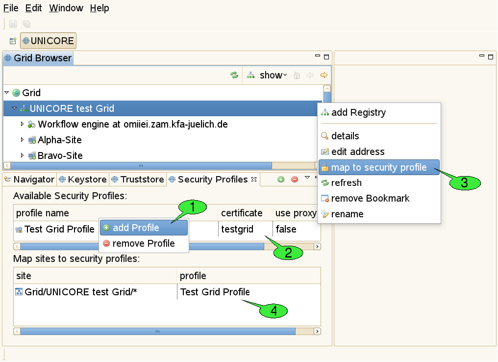
In order to configure the credentials to be used for a particular service, follow these steps (see [FIGURE_SECURITY_PROFILES]):
-
Create a new security profile 1.
-
Adjust all security settings for this profile to your needs, e.g. select a certificate 2, choose whether a proxy certificate shall be created (only needed for accessing services from other Grid middlewares like Globus).
-
Use the map to security profile action on the service in the Grid Browser view for creating a new site entry 3.
-
Select the new profile for the newly created site 4. Alternatively, you can reuse an existing profile and skip the steps 1-2.
Passing down credentials to child services works like this: for each site entry in the lower table of the Security Profiles view, the first column shows a pattern which matches a particular service. Using the wildcard character ‘*’ at the end of the pattern, the service’s children will be matched, too. For example, the pattern for a registry called ‘UNICORE test Grid’ looks like this:
Grid/UNICORE test Grid/*
Now imagine this registry contains a target system service called ‘Alpha-Site’. The Grid Browser displays the target system as a child node of the registry node. In order to determine which credentials to use for acessing this service, the path of node names from the target system node up to the top level node (called ‘Grid’) is determined and concatenated to form a single URL (the names are separated by slashes). In our example, this results in
Grid/UNICORE test Grid/Alpha-Site
Next, this URL is compared to all patterns that have been defined in the site entries. The longest name path pattern that matches the URL ‘Grid/UNICORE test Grid/Alpha-Site’ (i.e. the pattern that contains the most slashes) determines which security profile is used for the service. In our example, the pattern ‘Grid/UNICORE test Grid/*’ matches (because of the wildcard character).
Note: Due to the fact that the Grid is really a graph of services (not a tree), there can actually be multiple name paths for a given service. In this case, all name paths are matched against all patterns and again, the longest pattern wins. In case of two or more matched patterns with equal length, the choice of the ‘winning’ pattern is arbitrary.
6.3. Pull Down Menus
6.3.1. The File pull down menu
The File pull down menu gives access to a set of global functions. Frequently used functions are also available on the tool bar below the pull down menu line.
-
File → New allows to create Projects (e.g. workflow projects), and other objects. To create a new non-workflow project click File → New → Project. A new window is displayed ([FIGURE_NEW_PROJECT], left). Click Next. In the upcoming wizard page, type the name of the new project, e.g. Project1 and click Finish. A new sub-directory is created in the workspace. It is recommended not to change the default location. The data related with the project is stored in a subdirectory of the workspace that has the same name as the project. Experienced users may choose not to use the default location. Use the Browse button to locate an existing directory or to create a new one. Note that the Navigator view will show the projects not their location. If you specify a directory that already contains a project an error message is displayed.
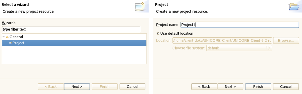 Figure 16: The New Project wizard
 -
File → New → Job Project is used for creating job descriptions. The job creation wizard will appear. Click Finish to automatically open the job editor. Do not change the file extension ‘.job’: otherwise a different file type is assumed and the wrong editor is invoked.
-
File → New → Workflow Project is used for creating workflow descriptions. The same dialog as before opens for providing a name for the new project (see [FIGURE_NEW_PROJECT], right). Click Finish to automatically open the workflow editor. Do not change the file extension ‘.flow’: otherwise a different file type is assumed and the wrong editor is invoked.
-
File → New → Other (see [FIGURE_NEW_OTHER_AND_OPEN_FILE], left) gives direct access to functions like creation of files, folders, projects, or workflows.
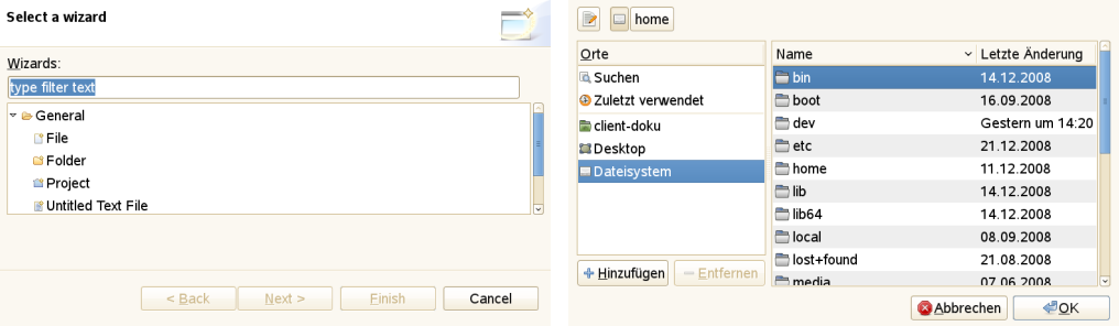 Figure 17: Creating and opening files
 -
File → Open File invokes the system file browser ([FIGURE_NEW_OTHER_AND_OPEN_FILE], right) and allows to open the selected file in the appropriate editor, depending on the file extension.
-
File → Save will copy a changed file to the original location. If the previously opened file has not been changed since the last SAVE, the function is not available.
-
File → Save as allows to save the file under a new name anywhere in the file system.
-
File → Save all saves all previously changed files.
-
File → Import allows you to import Eclipse projects from different source formats. This can be used for importing workflow projects which have been exported as file archives (zip or tar, see [FIGURE_IMPORT_ARCHIVE]). Additional Eclipse plugins may introduce additional types of projects and additional ways of importing such projects from external resources.
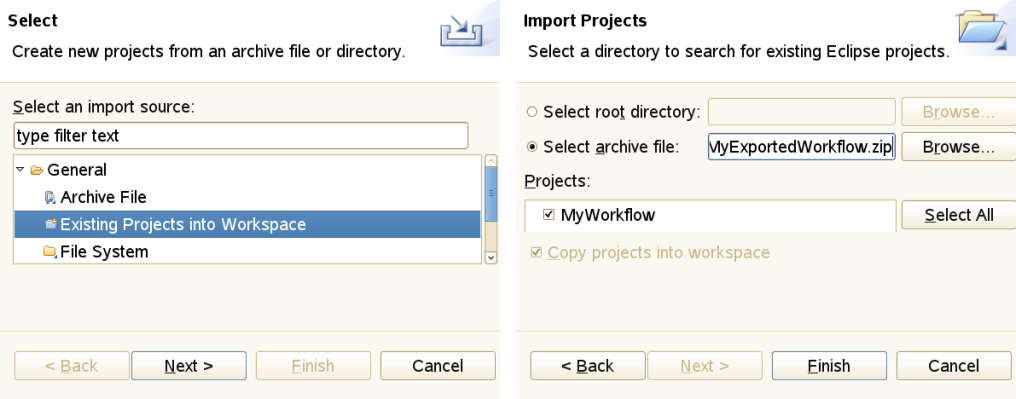 Figure 18: Importing an archived project
 -
File → Export can be used for exporting projects from your workspace to external resources. In order to export a project to a file archive, select General → Archive File and follow the instructions (see [FIGURE_EXPORT_ARCHIVE]).
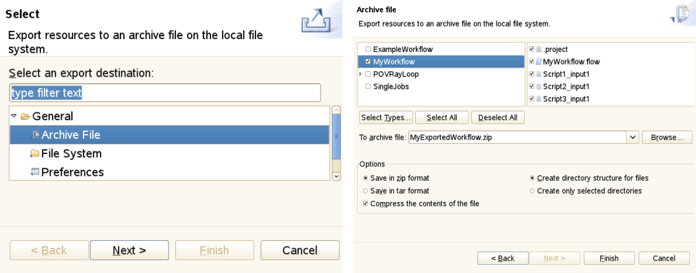 Figure 19: Exporting a project to an archive
 -
File → Properties is only available on some selected objects in the client. For instance, if you select a file in the Navigator view, this item becomes available. By clicking it, a dialog is activated that displays a number of properties of the file (e.g. its path, type, last modification date).
-
File → Exit terminates the client. If unsaved objects exist, you are prompted to save the changes.
6.3.2. The Edit pull down menu
-
Edit → Undo will undo the latest change that has been made in the editor that holds the focus.
-
Edit → Redo will redo the latest change that has been made in the editor that holds the focus. Only available when a change has been undone.
-
Edit → Cut is used to cut the selected items (e.g. text from a text editor or text field).
-
Edit → Copy will copy selected items to the clipboard.
-
Edit → Paste will paste items from the clipboard to the selected widget.
-
Edit → Find/Replace allows to search for all occurrences of a textual expression inside a widget that holds text and (optionally) replace it.
6.3.3. The Window pull down menu
The Window pull down menu allows to manage perspectives, views, and working sets. You may change preferences and alter the security configuration.
-
Window → Open Perspective shows the selected perspectives. Further perspectives may be activated by clicking on Other. A window opens listing the available perspectives. Clicking on the name, e.g UNICORE, followed by OK opens the perspective (see [FIGURE_SWITCH_AND_CUSTOMIZE_PERSPECTIVES], left).
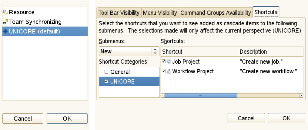 Figure 20: Switch and customize perspectives
 -
Window → Customise Perspective (see [FIGURE_SWITCH_AND_CUSTOMIZE_PERSPECTIVES], right) allows to change the appearance of a particular perspective. It can be used to hide or show icons on the tool bar or hide and show functions in the pull down menus. Warning: changing the defaults can create confusion and prevent efficient problem determination.
-
Window → Save Perspective As… allows for saving a modified copy under a different name). It is good practice to retain the original one.
-
Window → Reset Perspective restores a changed perspective to its default values. This is an extremely useful function if you have destroyed the familiar appearance through inadvertent mouse clicks.
-
Window → Close Perspective hides the selected perspective.
-
Window → Close All Perspectives hides all perspectives.
-
Window → Show View → Other… opens the list of available views. Selecting one of the views followed by OK opens the view. You may restrict the displayed views by typing part of the name in the box showing type filter text.
-
Window → Preferences this opens the preference pages for customising the way the UNICORE client works and appears. See [SUBSECTION_PREFERENCES] for a more detailed discussion of client preferences.
-
Window → Security Configuration opens the Keystore, Truststore and Security Profiles views for changing security related settings.
6.3.4. The Help pull down menu
The Help pull down menu allows to access details about the installed client software. It also allows to update the software from a distribution server.
-
Help → Welcome will re-open the client’s welcome screen (a series of HTML pages that is shown when the client is started for the first time). The welcome screen contains references to important help topics, first steps to perform in order to configure the client correctly, and links to online resources like the UNICORE project home or video tutorials covering the usage of the UNICORE Rich Client.
-
Help → About UNICORE Rich Client shows some version information about the client and its components. For example, clicking on Plugin Details shows detailed information about each software component (plugin in Eclipse terminology).
-
Help → Help Contents tries to open the HTML-based Eclipse help system in a web browser.
-
Help → Search allows for performing full text queries on the content of all help pages and lists the results.
-
Help → Dynamic Help opens a view that displays helpful information concerning a selected object in the client. Note that only some objects in the client provide helpful information on their usage.
-
Help → Software Updates → Find and Install… allows to update the Client and its components to the most current versions (see [FIGURE_UPDATE_CLIENT]). In order to perform an update, select Search for updates of the currently installed features. The search will then be performed. In the following dialog, select the features to be updated from the list of available features with updates.
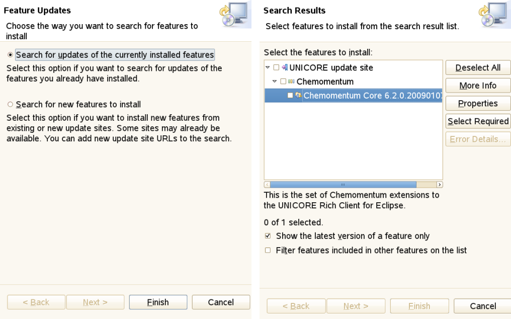 Figure 21: Update the client
 -
Help → Software Updates → Download Grid Applications can be used for downloading application specific graphical user interfaces (GUIs) from the Grid. It is only available if one or more services that offer such user interfaces could be found in the registries that have been added by the user. Application specific GUIs can be used in order to create job descriptions for single jobs or embedded jobs in workflows.
-
Help → Key Assist shows the table of available keyboard shortcuts that may be used in addition to the mouse.
6.4. Preferences
Each Eclipse-based application provides a set of pages for changing user preferences. The basic Eclipse framework already allows for the customisation of settings like colours and fonts to be used throughout the client or key bindings for certain actions. Additional plugins may extend the existing set of preferences. The UNICORE specific plugins use this mechanism for introducing a whole range of new options that determine their mode of operation. This section discusses these UNICORE-related preference settings.
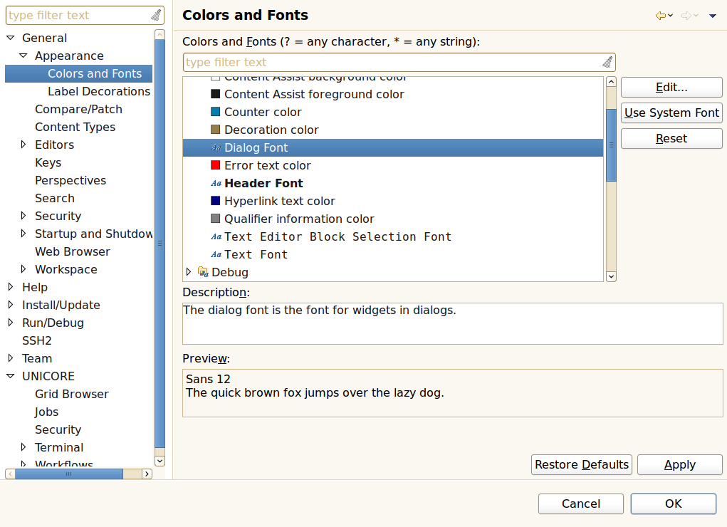
In order to manage a large set of different preferences, Eclipse organises them in categories that form a tree structure. This structure is shown to the left of the preferences panel and allows to select the category of options you wish to change. Depending on the selected category a different preference page opens on the right side of the panel. In the first example ([FIGURE_PREFERENCES_GENERAL]), the category Colours and Fonts has been selected. Clicking on Change… opens a font selector dialog. You may Apply the change or Restore Defaults. OK leaves the Preference Panel retaining the changes while Cancel leaves the panel and discards the changes.
6.4.1. General preferences for UNICORE
There is a dedicated preference category containing UNICORE related settings:
-
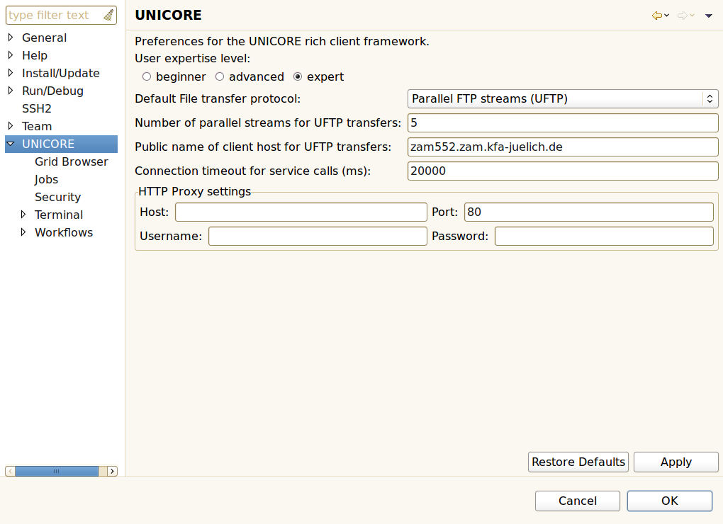
User Expertise Level: The client targets a wide range of users with varying experience and knowledge about the Grid. Switching to higher levels will reveal more details to the user and enable additional actions. The default is beginner.
-
Default File transfer protocol: Users can choose from different protocols for transferring files to and from UNICORE storages, e.g. the Baseline file transfer (a fast HTTP based protocol) and the OGSA Random Access ByteIO (a slower but widely supported protocol). Setting this to Automatic will try to auto-detect the fastest available protocol (note that this is only supported with UNICORE >= 6.4.2).
-
Number of parallel streams for UFTP transfers: UFTP is a high performance file transfer protocol that uses multiple parallel TCP streams for transmission. This setting determines the number of parallel streams. Caution, setting this too high might degrade performance, as merging the streams creates a certain overhead.
-
Public name of client host for UFTP transfers: The UFTP protocol requires the client to explicitly state it’s host name. The client tries to guess this value, thus it only needs to be changed if you experience problems with UFTP transfers.
-
Use encryption during UFTP transfers: Set this option to use encryption during file transfers when using UFTP protocol.
-
Connection timeout for service calls (ms): This option determines how quickly the client will give up when a server does not respond to its requests. The default is 20,000 milliseconds. Setting this value too low will prevent the client from communicating with Grid services altogether.
-
HTTP Proxy settings: If you connect to the internet via an HTTP proxy server, you can provide the connection details in this form.
6.4.2. Preferences for the Grid Browser
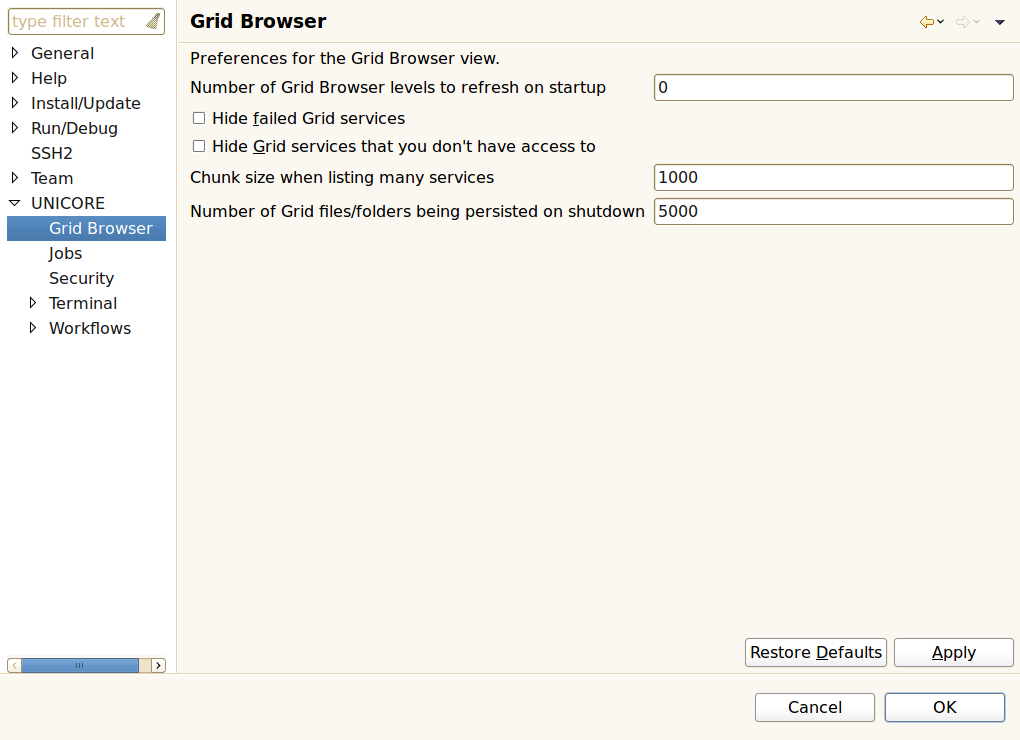
The following options can be found in the Grid Browser sub-category:
-
Number of Grid Browser levels to refresh on startup: An integer number specifying how many levels of services in the Grid Browser should be refreshed when the client is started. Refreshing means that the services are contacted in order to update cached information about them. Zero or negative numbers will prevent the Grid Browser from refreshing services during startup.
-
Hide failed Grid services: When enabled, this option will filter out all services that cannot be contacted by the client. These services will not be displayed in the Grid Browser anymore.
-
Hide Grid services that you don’t have access to: When enabled this will filter out all Grid services that could not be contacted due to access restrictions.
-
Chunk size when listing many services: Target systems can execute many jobs and Grid storages can contain lots of files. If the client just tried to list all jobs, services, and files on the Grid, it could easily run out of memory. Therefore, the number of child nodes displayed in the Grid Browser when refreshing its parent node is limited. Additional nodes can be displayed by double-clicking or expanding a node called ‘…’ which can be found at the end of the list of child nodes when the parent node seems to contain additional children. The number that is entered in this preference field determines the number of child nodes that are listed when first refreshing its parent and the number of nodes that are shown in addition, when the ‘…’ node is opened.
-
Number of Grid files/folders being persisted on shutdown: Grid storages may contain thousands of files. Persisting all associated Grid browser nodes to disk may use up a lot of disk space, and might increase startup and shutdown times.
6.4.3. Preferences for jobs
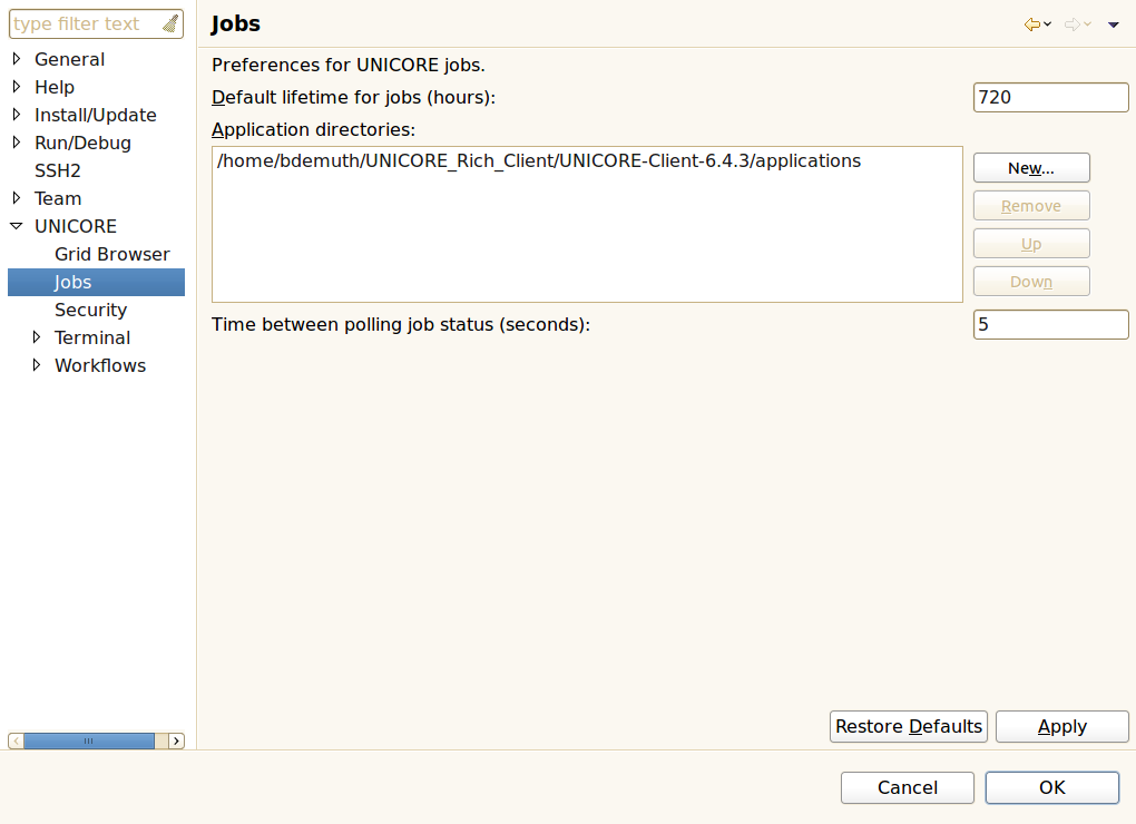
The following options can be found in the Jobs sub-category:
-
Default lifetime for jobs (hours): The amount of time after which submitted jobs are destroyed and cleaned up automatically. Once a job has been destroyed, its output files cannot be restored. This option can be overridden by setting the job’s lifetime in the Job Editor (see [SUBSUBSECTION_JOB_EDITOR]).
-
Application directories: A list of directory locations that hold application specific user interfaces that have been installed so far. New user interfaces for applications can either be downloaded from the Grid (see [SUBSUBSECTION_PULL_DOWN_HELP]) or manually copied to one of these directories. When interfaces are downloaded by the client, the user interface packages are put into the first directory in this list.
-
Time between polling job status: In monitoring mode, the job editor occasionally polls for changes in the submitted job’s execution status until the job has finished or failed. This option will set the amount of time until the next status check occurs.
6.4.4. Security preferences
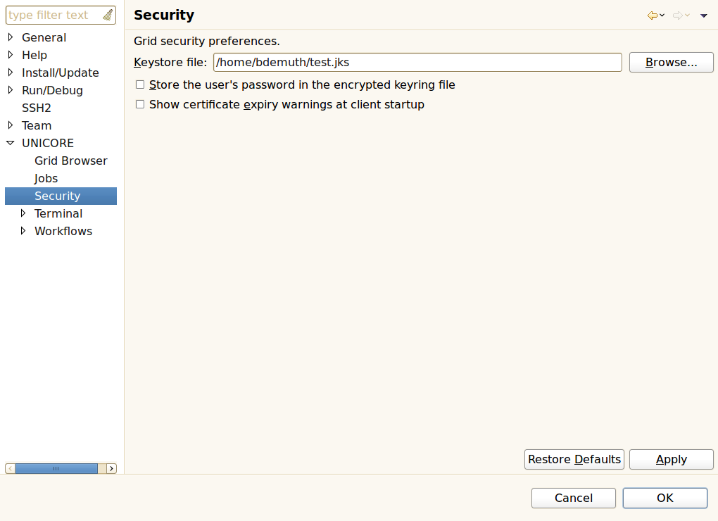
The following options can be found in the Security sub-category:
-
Keystore file: The location of the Java keystore (.jks) file to be used for holding the user’s private keys and the trusted certificates. The location can be changed by either directly entering a new path or clicking the Browse button, which opens a file browser.
-
Store the user’s password in the encrypted keyring file: Users have frequently asked for a way to start the client without having to supply the same password each time. When this preference is set to true, the client will save the user’s password in an encrypted file managed by Eclipse, the so-called keyring file. However, using this feature is NOT RECOMMENDED by the UNICORE team, as it weakens the security model of the Grid: An intruder will be able to take over a user’s Grid identity simply by starting the client.
-
Show certificate expiry warnings at client startup: When this option is enabled, the client will issue a warning during startup for each certificate that has expired or will expire soon.
6.4.5. Preferences for terminal connections
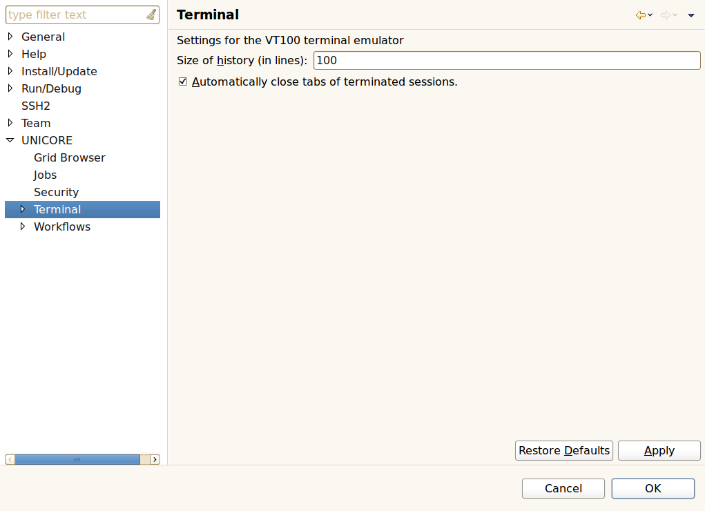
The following options can be found in the Terminal sub-category:
-
Size of history (in lines): The terminal view keeps a certain amount of lines in memory so the user can scroll up to see previous commands and outputs.
-
Automatically close tabs of terminated sessions: When a terminal session ends (e.g. when the user types "exit") the corresponding tab in the terminal view can be closed automatically.
6.4.6. Preferences for workflows
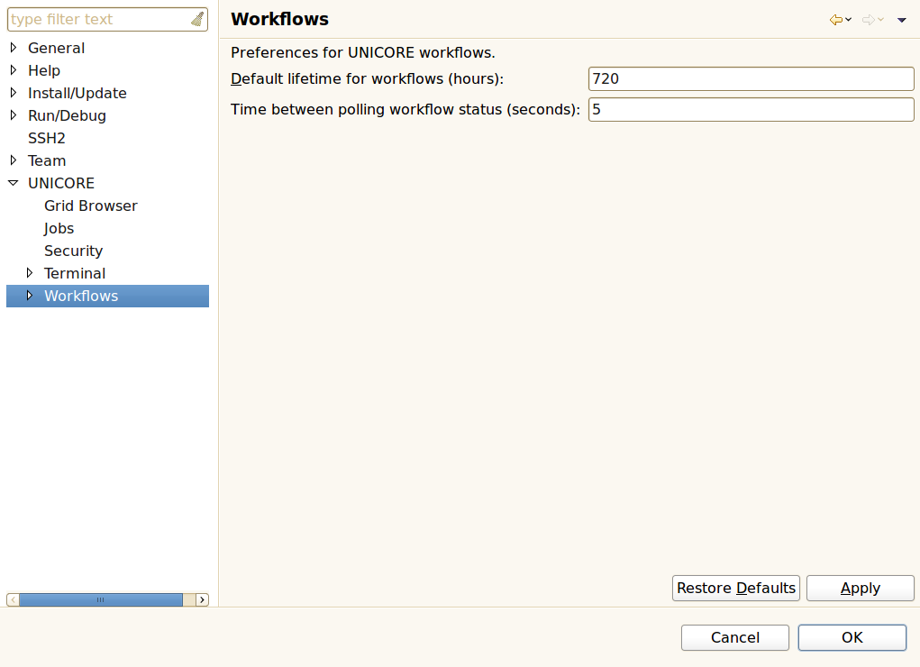
The following options can be found in the Workflows sub-category:
-
Default lifetime for workflows: The amount of time after which submitted workflows are being destroyed and cleaned up automatically. All jobs that have been submitted during workflow execution are cleaned up as well.
-
Time between polling workflow status: In monitoring mode, the workflow editor occasionally polls for changes in the submitted workflow’s execution status until the workflow has finished or failed. This option will set the amount of time until the next status check occurs.
6.5. Optional command line arguments
This is a selection of additional command line options that alter the behaviour of the client.
| Option | Effect |
|---|---|
-configuration path |
The path of the configuration folder containing basic configuration files and the user’s encrypted keyring file which might be used for storing passwords. |
-data path |
The path of the workspace on which to run the client platform. The workspace location is also the default location for projects. |
-vm path |
The location of Java Runtime Environment (JRE) to use to run the client platform. |
-vmargs args |
When passed to the client, this option is used to customise the operation of the Java VM used to run the client. If specified, this option must come at the end of the command line. The given arguments are dependent on the VM that is being run. VM arguments can also be added to the end of the UNICORE_Rich_Client.ini file, one per line. |
Examples:
-
Use c:\myProjects as workspace directory:
UNICORE_Rich_Client.exe -data c:\myProjects
-
Java is installed at c:\jre\bin:
UNICORE_Rich_Client.exe -vm c:\jre\bin
-
Allow the Java heap to use up to 256 MB of memory:
UNICORE_Rich_Client.exe -vmargs -Xmx256M
7. Glossary
- CA
-
Certification Authority: An entity which issues digital certificates for use by other parties. CA’s are characteristic of many public key infrastructure (PKI) schemes.
- GUI
-
Graphical User interface: A set of visual controls that steer a computer program. In contrast to a command line interface, it usually requires less typing because most actions can be performed via mouse clicks.
- HTTP
-
Hypertext Transfer Protocol: A communications protocol. Its use for retrieving inter-linked text documents (hypertext) led to the establishment of the World Wide Web.
- JRE
-
Java Runtime Environment: A set of computer programs and data structures which use a virtual machine model for the execution of JAVA programs.
- OGSA
-
Open Grid Services Architecture: An architecture of interacting services. It was described in the paper ‘The Physiology of the Grid – An Open Grid Services Architecture for Distributed Systems Integration’ and combines ideas and technologies from both Web- and Grid Services to provide a basis for service oriented Grid architectures (see http://www.globus.org/alliance/publications/papers/ogsa.pdf).
- SSL
-
Secure Sockets Layer: A widespread cryptographic protocol for securing connections on the internet. Uses Public key encryption for certificate-based authentication and symmetric cipher-based traffic encryption.
- XML
-
Extensible Markup Language: A text format derived from the Standard Generalized Markup Language (ISO 8879, see http://www.iso.org). XML is used to exchange data on the Web and it is the basis for a variety of languages and protocols (http://www.w3.org/XML/).
- SOA
-
Service Oriented Architecture: A software architecture that defines the use of software services to support the requirements of business processes and users on a computer network. The underlying paradigm emphasizes the definition of slim and platform-independent communication interfaces in order to achieve loose coupling. The SOA Reference Model provided by the OASIS Committee Specification, can be found at http://www.oasis-open.org/committees/tc_home.php?wg_abbrev=soa-rm.